
IMS Featured Products
Click on a featured products below for more information.
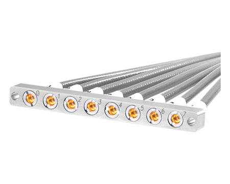
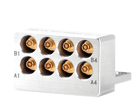
SMPM-G Gang
Mounts
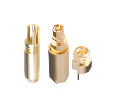
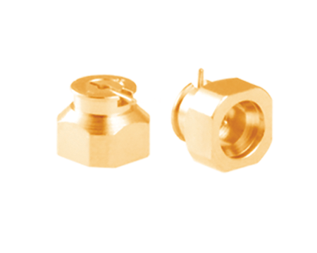
SMP-T / SMPM-T
/ SMP3-T
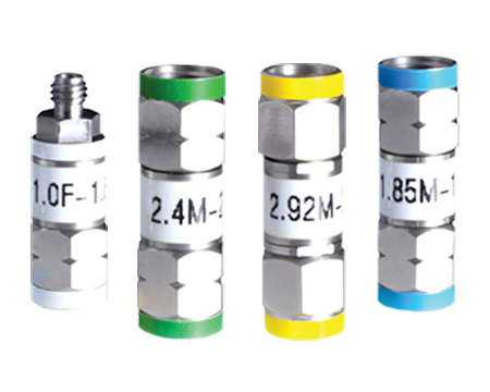
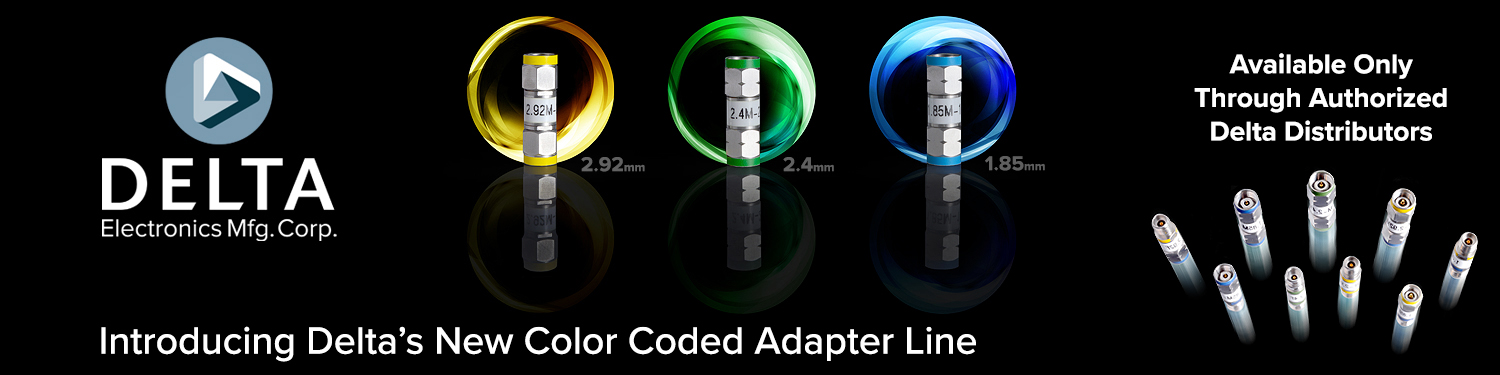
Color Coded
Adapters
SMP / SMPM
SMP3
General
Catalog
Cable
Assembly
Vita
Catalog
Mil-Spec
Catalog
Thank you for visiting our website. Please use chat or email sales@deltarf.com and tell us what you are looking for. Include interface type (SMA, SMP, SMPM, etc.), gender (plug or jack), operating frequency, cable mount or PCB mount, straight or right angle, mounting style (flange or BH mount) and plating preference (gold, passivated, nickel, albaloy) and our product experts will send you design options. Please also include quote quantity and lead time requirements. Thank you for the opportunity.
Markets Served
From avionics to audio, radar to robotics, Delta delivers precision interconnect and innovative solutions to a broad range of industries where reliability, performance, and durability are of paramount importance. Delta products are found in mission critical systems across our nation’s armed services, and platforms including homeland security, border control and NATO.
Click on an industry for more Delta information.

Aerospace

Broadcast / Audio

Communication

Industrial

Medical

Military

Test & Measurement
Transportation
Delta Mission Statement
We listen to our customers, and our employees, to assure our products are designed and manufactured for military and commercial marketplace utilization for today and tomorrow.
Delta Product Line
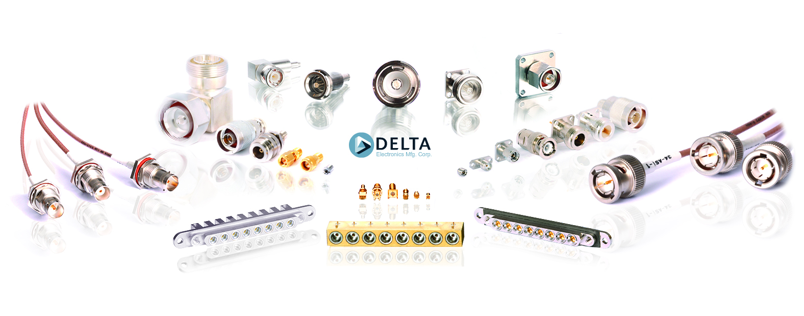
We deliver the key interconnect solutions you need to optimize the connectivity of your design
![]()
Communication
![]()
High Standards
![]()
Collaboration
![]()
RF Solutions
![]()
Expertise
![]()
Precision Design
US Headquarters
Delta Electronics Mfg. Corp.
416 Cabot St.
PO Box 53
Beverly, MA 01915
Phone: 978-927-1060
Fax: 978-922-6430
China Headquarters
Delta Microwave Electronics
(Nanjing) Co., Ltd.
No. 15 Ming Rui Road
Nanjing 211151, China
Phone: +86 25 84195408
Fax: +86 25 84195407
Support
Need Technical Support?
Have A Customer Service Question?
Please call 978-927-1060.
Available 8:00AM - 4:45PM EST M-F.
If after hours, please use our contact page, thank you.